Volvo Secondary Air Injection System Testing/Repair

Secondary air system (SAS) is an emissions control feature that pushes air into the exhaust to increase catalyst heating and to help burn up hydrocarbons and carbon monoxide. A SAS valve which won’t open (frozen or lacking full control vacuum) will result in a P0410 error code. Aged, cut, cracked vacuum elbows, couplers and lines are common problems/solutions.

Components:
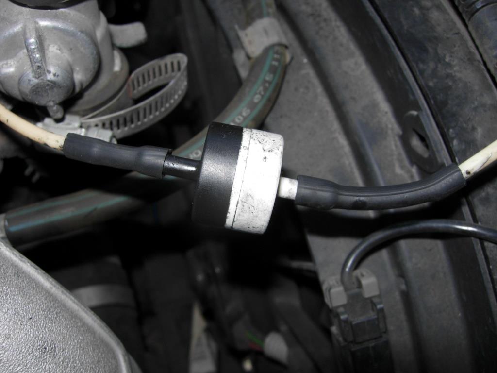
SAS vacuum check valve
SAS air injection pump
SAS valve

SAS air pump relay


SAS solenoid valve


Testing:
Ensure all fuses are okay, battery voltage is at least 11.5 volts, all electrical accessories are off, A/C is off. Ensure engine is mechanically sound.
1. With the car off and cold check hoses and components of Secondary Air Injection System, for damage, loose fit and improper installation, check vacuum hoses of Secondary Air Injection System. Repair as necessary. Erase DTC (Diagnostic Test Codes) memory. Verify repair. If DTC does not reset, test is complete.
2. The SAS valve is tested on the car. With the car off and cold, disconnect the small vacuum hose at the valve. Disconnect the large hose from the valve.  Using another piece of hoses, (you will be blowing and sucking on these, so make sure you have enough length) connect one to the small port and the other two the large port. First, try blowing into the large hose, you should not be able to, it should be closed.  Then using a vacuum pump or someone else, such on the small hose (this should open the valve) now blow into the large hose (you should be able to blow). If either fails, replace the valve. A secondary test is with the car running: Disconnect the large hose from the valve, the valve should not leak exhaust out the hose fitting toward the air pump. Suck on the small hose it should open.
3. The check valve is tested similarly. With the car off and cold, disconnect the check valve, try alternating blowing and sucking on each end.  If it fails, replace it. NOTE the properly placement in the line (DO NOT REVERSE).
4. The air pump relay switches the high-powered pump motor on and off with a low level signal from the ECM.  Newer 850 models have the relay attached to the pump while older models have the relay mounted nearby.  Relays can fail or have connection problems which cause the air pump to not operate.
5. Verify with engine running, there is sufficient vacuum to the solenoid, activate the solenoid to see if the vacuum gets to the check valve. If not, check for broken hoses.
6. It is possible to check the air pump by supplying power directly to it.  Check your wiring diagram for info. Use a fused jumper.  It works or it does not.

Volvo 850 Strut nut socket


850 sway bar bushing replacement

To keep your sway bar from "walking" or sliding left and right after bushing replacement, try using shaft collars or other clamps. 

You  should lower the suspension to replace the bushings, however it can be done at much greater work and time without lower it.

Volvo 850 shock job

Drivers side rear shock top mount location

Detail of rear shock

Passenger side closeup of upper shock mount and location

Access to upper shock mounts and bolts is behind the rear seat. Before attempting to remove the upper bolt, clean threads with wire brush, spray well with penetrating oil, use special shock bolt socket or a pair of vise grips on the oval top of the shock bolt. As the nut comes off spray again with oil. DO NOT remove the lower mount first, as this will help hold the shock while the upper nut is removed.

Pics showing upper rear shock mounts and style of shocks.

850 rear disk removed

Rear rotor removed to expose the  parking brake. Note: the locating pin is screwed back in the Hub to prevent its loss.

Posted via Blogaway

Bad sway bar links

The sway bar or anti roll bar connecting links were bad. One  ball joint had completely disintegrated.

Posted via Blogaway


Posted via Blogaway

Vlovo 850 timing belt job


The following are just photos of the radiator job that I was doing also, I'll move them later.


This job will take approximately 4 hours assuming you have all the required tools and the parts available at hand. A complete timing belt kit which includes the water pump is between $150 and $250 depending upon where you shop. 
 

The following instructions assume that you were be replacing all of the components, including the water pump.

Removal
Before disconnecting the negative battery cable, make sure you have the correct activation code for the stereo if you have an anti-theft system. Disconnect the negative battery cable.

Set parking brake and block the rear wheels.
Raise and safely support front of vehicle.
Drain the cooling system.
Remove the following:
Spark plug cover.
Fuel pipe clip at top of timing cover.
Coolant reservoir placing it to one side.
Right hand front wheel. Inside the tire well, raise the inner cover in the back covering the crankshaft bolt.
Modular box snorkel.
The serpentine belt.
Front of timing case cover.
Remove the timing belt guard plate located behind behind the crankshaft pulley.
Remove the spark plugs or loosen them severely to allow the engine to turn without compression.
Look over all the components (both on the car and the new ones) and identify were they are and how many bolts they have and/or take a photo now.
Pay special attention to identifying and safe guarding the auto tensioner restricting washer which may not be included in the kit.
Using a socket and the crankshaft pulley bolt rotate the crankshaft  clockwise until the three timing marks align as required (best to check twice).

Remove the upper timing case cover (covers the top of the camshaft gears). 
At this point, you can either cut the belt and remove it or remove the belt by first removing the tensioner. Either way will work.
Once the belt is removed, spin using your hand the various pulleys to check for noise or roughness, if you have the kit, just remove them as you will be replacing them.
Clean the area, before removing the water pump to prevent dirt and cleaning fluid entering the engine.
Remove the water pump and remove any gasket meterial remaining on the engine.


More to follow

Where to connect the jumper cables

Volvo 850 jumper cable location

  • If the booster battery to be used is in another car, check that the cars are not touching to prevent premature completion of negative circuit. Note the position of the battery terminals and using jumper cables:
  • First connect the booster battery positive (+) terminal (1) to car battery positive (+) terminal (2).

  • Then connect the booster battery negative (-) terminal (3) to a stationary solid metal part on the engine at a point away from the battery (4).

    Do not connect booster cable to any part of fuel system or any moving parts. Avoid touching hot manifolds.
    After the engine has started, first remove the negative (-) terminal jumper cable. Then remove the positive (+) terminal jumper cable.
  • Volvo 850 Charging problem

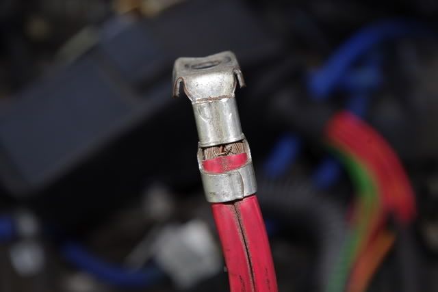
     On cars of this type and age, the crimp on the positive terminal can fail turning the positive wire to the battery into a resistor rather than a wire.  This is diagnosed by measuring the charging voltage on the battery and giggling the wire (it will jump around, and not remain at the required 13.8 V), and by noticing that the wire itself is hot.  Volvo recently released a fix for this, and previously the shop had to remove the entire wiring harness, at great expense, to fix it. 


    850 fuel tank gauge info


    The fuel tank holds approximately 19.3 US gals. (73 liters). When the warning light comes on, there is approximately 1.8 US gals. (8 liters) of fuel remaining in the tank. When it reads empty, your screwed.

    850 Owners manual


    Get one HERE.

    850 Volvo Brake specs

    DISC BRAKE SPECIFICATIONS TABLE
    Application In. (mm) Disc Diameter
    Front ……………………………….. 11.02 (280)
    Rear ………………………………… 11.61 (295) Lateral Runout (Maximum)
    Front ………………………………… .001 (.04) Rear …………………………………. .003 (.08)
    Original Thickness
    Front …………………………………. 1.02 (26) Rear ………………………………….. .38 (9.6) Minimum Refinish Thickness …………………….. (1)
    Discard Thickness
    Front ………………………………….. .90 (23) Rear ………………………………….. .33 (8.4)
    Parking Brake Drum (Inside Rotor)
    Maximum Runout ………………………….. .006 (.15)
    (1) – Always use minimum thickness specification stamped on rotors.

    Volvo pressure bleeding tricks

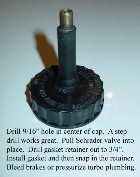
    Use the above modified cap with a bicycle pump.

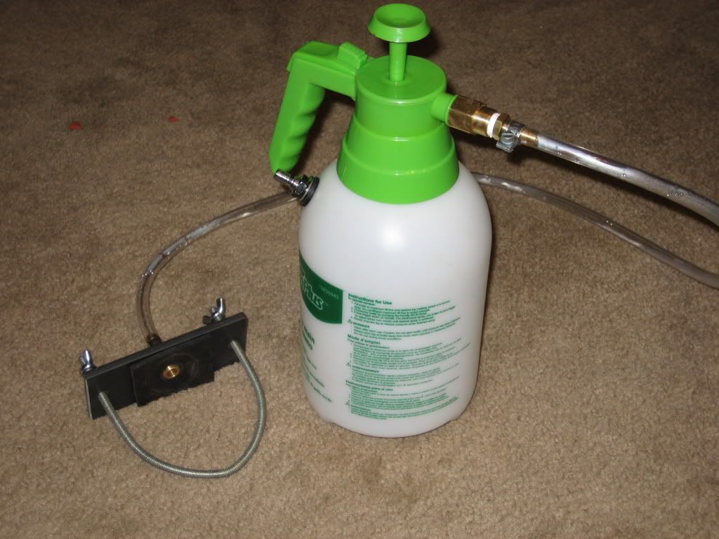
    Home-Made Pressure Bleeder. [TV Pierce] You can make your own pressure bleeder. Power Motive's is nothing more than a garden sprayer with a brake reservoir cap attached to the end of the tube instead of a spray nozzle (they also add a pressure guage -- but it's not really necessary). The sprayer is about $10 at Home Depot, and a new reservoir cap should be $2-$3 at FCP Groton. Drill a hole through the cap, epoxy a tube fitting through the hole, then cut off the spray nozzle, and attach the reservoir cap.
    [Gary Gilliam] I made mine out of a cheap all plastic 4 liter ( about $13) garden sprayer, and an old master cap. I cut the hose just above the sprayer wand, attached a 5/16" brass fitting that is commonly used for repairing air lines: it is barbed on one end to stick inside the hose and has 1/4" NPT threads on the other. This was secured to the hose with a stainless hose clamp and a 1/2" hole was drilled in the extra master cylinder cap to receive the other end of the fitting. The fitting was secured to the cap with a 1/2" long brass NPT straight connector, adding a rubber washer on both sides coated in RTV for good measure. I was going to add a pressure gauge, but never got around to it. It seems to work fine with just enough pumps to get things moving a bit.

    Sucking out the old fluid- Turkey baster

    Pressure bottle. Learn how to make it HERE.


    Volvo 850 Bleeding the brakes

    Bleeding hose attached

    NOTE: Use only DOT 4 grade brake fluid.

    1) Raise and support vehicle. Fill master cylinder reservoir
    to maximum mark. Bleed brakes in sequence. See
    BRAKELINE BLEEDING SEQUENCE. After bleeding brakes, depress
    brake pedal with a force equal to an abrupt stop.

    2) Pedal travel should not exceed 1.57" (40 mm). Brake
    warning light should not illuminate. If air is still present in
    system, repeat procedure.

    BRAKELINE BLEEDING SEQUENCE TABLE
    850 ..................................... LR Or RR, RF, LF

    The adventure begins


    The Car

    Volvo Man's daily ride.
    Formerly just a normal 1996 850. A few enhancements were made for the commute to crime stopper central, Volvo Man's nation wide crime buster electronic network in Valley Forge.

    Various Volvo 850 parts

    Torque Rod Bushing (suspension bushing)

    Front Strut

    ABS Module


    Volvo 850 VIN information

    MODEL IDENTIFICATION

    VIN LOCATION

    The Vehicle Identification Number (VIN) is located on the
    left side of the dash panel at the base of the windshield. The VIN
    chart explains the code characters.

    VIN CODE ID EXPLANATION

    Numbers preceding the explanations in the legend below refer
    to the sequence of characters as listed on VIN identification label.

    See VIN example below.

     (VIN) Y V 1 L S 5 5 1 X P  1    0   0   0   0   0   1

               1  2 3 4 5 6 7 8 9  10 11 12 13 14 15 16 17


    1 - Manufacturing Country

           Y  *Sweden Or Belgium

    2 - Manufacturer

           V  *Volvo

    3 - Vehicle Type

           1  *Passenger Vehicle

    4 - Vehicle Series

           L  *850 Sedan

    5 - Body Style & Restraint System

        S  *850 4-Door Sedan W/ Driver & Passenger Airbags
        S  *850 4-Door W/ Dual Airbags & Pretentioners
        W  *850 5-Door Wagon W/ Driver & Passenger Airbags

    6-7 - Engine Type

        55  *B5254S 2.4L 5-Cylinder
        57  *B5234T 2.3L Turbo 5-Cylinder
        58  *B5234T5 2.3L Turbo 5-Cylinder

    8 - Emission Control System

        0  *Three-way Converter, Heated Oxygen Sensor, W/O EGR
        1  *Three-way Converter, Heated Oxygen Sensor, W/EGR
        2  *Three-way Converter, Heated Oxygen Sensor, W/EGR, Airpump

    9 - VIN Check Digit

        *Computer Generated

    10 - Vehicle Model Year

        P  *1993
        R  *1994
        S  *1995
        T  *1996

    11 - Assembly Plant

        0  *Kalmar, Sweden
        1  *Torslanda, Sweden
        2  *Ghent, Belgium
        3  *Halifax, Nova Scotia, Canada
        A  *Uddevalla, Sweden

    12-17 - Serial Number
        *Sequential Production Number

    Volvo 850 timing belt replacement

    2.4L 1996 
    ENGINE IDENTIFICATION
    Engine may be identified by using Vehicle Identification
    Number (VIN) stamped on a metal pad, located near lower left corner of
    windshield. The sixth and seventh character identifies engine model.
    Engine identification number, located on left side of
    cylinder block below cylinder head, may be required when ordering
    replacement parts.
    ENGINE IDENTIFICATION CODES TABLE
     ✁ ✁ ✁ ✁ ✁ ✁ ✁ ✁ ✁ ✁ ✁ ✁ ✁ ✁ ✁ ✁ ✁ ✁ ✁ ✁ ✁ ✁ ✁ ✁ ✁ ✁ ✁ ✁ ✁ ✁ ✁ ✁ ✁ ✁ ✁ ✁ ✁ ✁ ✁ ✁ ✁ ✁ ✁ ✁ ✁ ✁ Engine Code
    2.4L (Non-Turbo) ...................................... 55
     ✁ ✁ ✁ ✁ ✁ ✁ ✁ ✁ ✁ ✁ ✁ ✁ ✁ ✁ ✁ ✁ ✁ ✁ ✁ ✁ ✁ ✁ ✁ ✁ ✁ ✁ ✁ ✁ ✁ ✁ ✁ ✁ ✁ ✁ ✁ ✁ ✁ ✁ ✁ ✁ ✁ ✁ ✁ ✁ ✁ ✁ 
    CAUTION:Failure to replace a faulty camshaft timing belt may result
    in serious engine damage.

    The condition of camshaft drive belts should always be
    checked on vehicles which have more than 50,000 miles. Although some
    manufacturers do not recommend belt replacement at a specified
    mileage, others require it at 60,000-100,000 miles. A camshaft drive
    belt failure may cause extensive damage to internal engine components
    on most engines, although some designs do not allow piston-to-valve
    contact. These designs are often called "Free Wheeling".
    Many manufacturers changed their maintenance and warranty
    schedules in the mid-1980’s to reflect timing belt inspection and/or
    replacement at 50,000-60,000 miles. Most service interval schedules in
    this manual reflect these changes.

    Belts or components should be inspected and replaced if any
    of the following conditions exist:
    *Cracks Or Tears In Belt Surface
    *Missing, Damaged, Cracked Or Rounded Teeth
    *Oil Contamination
    *Damaged Or Faulty Tensioners
    *Incorrect Tension Adjustment
    Volvo recommends replacement of the camshaft timing belt at
    the following intervals:

    CAMSHAFT TIMING BELT REPLACEMENT INTERVAL TABLE
    Application Interval (Miles)
    1993 ................................................... 50,000
    1994-96 ................................................ 70,000


    TIMING BELT
    Removal
    1) Remove spark plug cover and 2 fuel line clips. Lift out
    expansion tank and place on top of engine. Remove front timing belt
    cover. Remove auxiliary drive belt. Remove right front wheel and
    release wheel arch liner to gain access to vibration damper. Remove
    vibration damper guard. Turn crankshaft clockwise until all timing
    marks are aligned. See Fig. 8.
    2) Remove tensioner upper mounting bolt and loosen tensioner
    lower bolt. Twist tensioner to free pulley. Remove lower bolt,
    tensioner, upper timing belt cover and belt.
    3) Remove tensioner upper mounting bolt and loosen lower
    mounting bolt. Twist tensioner to free plunger/pulley. Remove lower
    bolt, tensioner and belt.
    CAUTION:DO NOT turn crankshaft or camshafts while belt is removed.
    Inspection
    1) Spin tensioner and idler pulleys and listen for bearing
    noise. See Fig. 11.
    2) Ensure pulley surfaces in contact with belt are clean and
    smooth. Check tensioner pulley arm and idler pulley mountings, and
    tighten bolts as necessary. See  TORQUE SPECIFICATIONS. Check tensioner
    for signs of leakage, no resistance when depressed, or a plunger that
    cannot be depressed.

    Installation
    1) Compress tensioner and tighten center nut. Wait until
    compression has taken place and insert a 2 mm locking pin in plunger.


    Install tensioner and tighten mounting bolts to 18 ft. lbs. (25 N.m).
    Place timing belt around crankshaft pulley and right idler. Place belt
    over camshaft pulleys. Position belt around water pump and press over
    tensioner pulley.


    2) Rapidly remove tensioner locking pin. 

    To complete installation,
    reverse removal procedure. Turn crankshaft 2 revolutions to ensure
    timing marks on crankshaft and camshaft pulleys are aligned.


    WATER PUMP
    Removal
    Remove expansion tank cap and drain coolant. Remove timing
    belt. See TIMING BELT. Remove bolts holding water pump to engine
    block. See Fig. 13. Remove water pump.
    Installation
    Remove old gasket from cylinder block. Install water pump.
    Tighten mounting bolts alternately to 15 ft. lbs. (20 N.m). Install
    timing belt. See TIMING BELT. Fill engine with coolant. Start engine
    and check for leaks.